2003 Nissan Pathfinder Ignition Wiring Diagram
Content .. 222 223 224 225 ..
Nissan Pathfinder (2006 year). Manual - part 224

IGNITION SIGNAL
EC-651
C
D
E
F
G
H
I
J
K
L
M
A
EC
2006 Pathfinder
BBWA2378E

EC-652
IGNITION SIGNAL
2006 Pathfinder
Specification data are reference values and are measured between each terminal and ground.
Pulse signal is measured by CONSULT-II.
CAUTION:
Do not use ECM ground terminals when measuring input/output voltage. Doing so may result in dam-
age to the ECM's transistor. Use a ground other than ECM terminals, such as the ground.
: Average voltage for pulse signal (Actual pulse signal can be confirmed by oscilloscope.)
Diagnostic Procedure
UBS00KHX
1.
CHECK ENGINE START
Turn ignition switch OFF, and restart engine.
Is engine running?
Yes or No
Yes (With CONSULT-II)>>GO TO 2.
Yes (Without CONSULT-II)>>GO TO 3.
No
>> GO TO 4.
2.
CHECK OVERALL FUNCTION
With CONSULT-II
1.
Perform "POWER BALANCE" in "ACTIVE TEST" mode with
CONSULT-II.
2.
Make sure that each circuit produces a momentary engine
speed drop.
OK or NG
OK
>>INSPECTION END
NG
>> GO TO 10.
TER-
MINAL
NO.
WIRE
COLOR
ITEM
CONDITION
DATA (DC Voltage)
79
80
81
P
GR
G
Ignition signal No. 6
Ignition signal No. 4
Ignition signal No. 2
[Engine is running]
●
Warm-up condition
●
Idle speed
NOTE:
The pulse cycle changes depending on rpm
at idle
0 - 0.2V
[Engine is running]
●
Warm-up condition
●
Engine speed: 2,500 rpm
0.1 - 0.4V
SEC986C
SEC987C
PBIB0133E
IGNITION SIGNAL
EC-653
C
D
E
F
G
H
I
J
K
L
M
A
EC
2006 Pathfinder
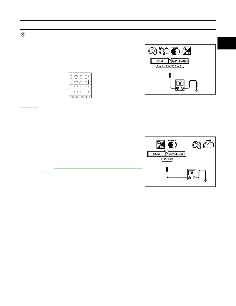
3.
CHECK OVERALL FUNCTION
Without CONSULT-II
1.
Let engine idle.
2.
Read the voltage signal between ECM terminals 60, 61, 62, 79,
80, 81 and ground with an oscilloscope.
3.
Verify that the oscilloscope screen shows the signal wave as
shown below.
NOTE:
The pulse cycle changes depending on rpm at idle.
OK or NG
OK
>>INSPECTION END
NG
>> GO TO 10.
4.
CHECK IGNITION COIL POWER SUPPLY CIRCUIT-I
1.
Turn ignition switch OFF, wait at least 10 seconds and then turn ON.
2.
Check voltage between ECM terminals 119, 120 and ground
with CONSULT-II or tester.
OK or NG
OK
>> GO TO 5.
NG
>> Go to
EC-145, "POWER SUPPLY AND GROUND CIR-
CUIT"
.
PBIB1186E
SEC986C
Voltage: Battery voltage
MBIB0034E

EC-654
IGNITION SIGNAL
2006 Pathfinder
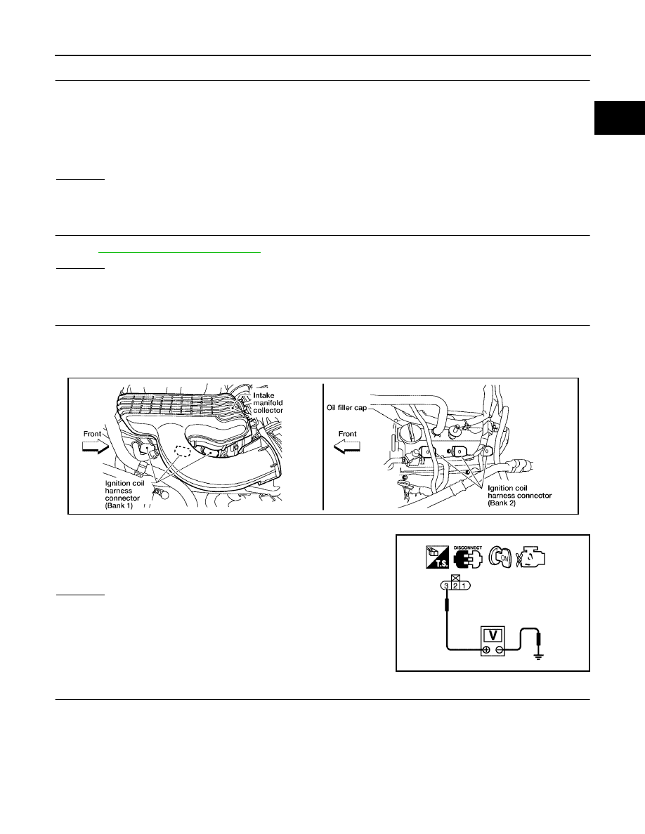
5.
CHECK IGNITION COIL POWER SUPPLY CIRCUIT-II
1.
Turn ignition switch OFF.
2.
Disconnect condenser-1 harness connector.
3.
Turn ignition switch ON.
4.
Check voltage between condenser-1 terminal 1 and ground with
CONSULT-II or tester.
OK or NG
OK
>> GO TO 8.
NG
>> GO TO 6.
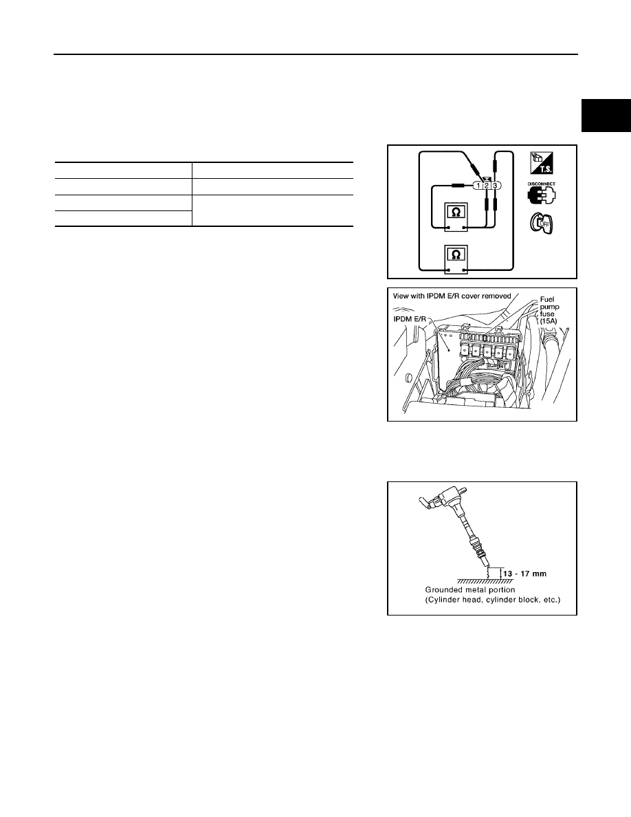
6.
CHECK IGNITION COIL POWER SUPPLY CIRCUIT-III
1.
Turn ignition switch OFF.
2.
Disconnect IPDM E/R harness connector E119.
3.
Check harness continuity between IPDM E/R terminal 3 and condenser-1 terminal 1.
Refer to Wiring Diagram.
4.
Also check harness for short to ground and short to power.
OK or NG
OK
>> GO TO 17.
NG
>> GO TO 7.
7.
DETECT MALFUNCTIONING PART
Check the following.
●
Harness connectors E2, F32
●
Harness for open or short between condenser-1 and IPDM E/R
>> Repair open circuit or short to ground or short to power in harness or connectors.
BBIA0562E
Voltage: Battery voltage
PBIB0624E
Continuity should exist.
IGNITION SIGNAL
EC-655
C
D
E
F
G
H
I
J
K
L
M
A
EC
2006 Pathfinder
8.
CHECK CONDENSER-1 GROUND CIRCUIT FOR OPEN AND SHORT
1.
Turn ignition switch OFF.
2.
Check harness continuity between condenser-1 terminal 2 and ground.
Refer to Wiring Diagram.
3.
Also check harness for short to power.
OK or NG
OK
>> GO TO 9.
NG
>> Repair open circuit or short to power in harness or connectors.
9.
CHECK CONDENSER-1
Refer to
EC-657, "Component Inspection"
.
OK or NG
OK
>> GO TO 10.
NG
>> Replace condenser-1.
10.
CHECK IGNITION COIL POWER SUPPLY CIRCUIT-V
1.
Turn ignition switch OFF.
2.
Reconnect all harness connectors disconnected.
3.
Disconnect ignition coil harness connector.
4.
Turn ignition switch ON.
5.
Check voltage between ignition coil terminal 3 and ground with
CONSULT-II or tester.
OK or NG
OK
>> GO TO 12.
NG
>> GO TO 11.
11.
DETECT MALFUNCTIONING PART
Check the following.
●
Harness connectors F26, F125
●
Harness for open or short between ignition coil and harness connector F32
>> Repair or replace harness or connectors.
Continuity should exist.
Voltage: Battery voltage
BBIA0561E
PBIB0138E

EC-656
IGNITION SIGNAL
2006 Pathfinder
12.
CHECK IGNITION COIL GROUND CIRCUIT FOR OPEN AND SHORT
1.
Turn ignition switch OFF.
2.
Check harness continuity between ignition coil terminal 2 and ground.
Refer to Wiring Diagram.
3.
Also check harness for short to power.
OK or NG
OK
>> GO TO 14.
NG
>> GO TO 13.
13.
DETECT MALFUNCTIONING PART
Check the following.
●
Harness connectors F125, F26
●
Harness for open or short between ignition coil and ground
>> Repair open circuit or short to power in harness or connectors.
14.
CHECK IGNITION COIL OUTPUT SIGNAL CIRCUIT FOR OPEN AND SHORT
1.
Disconnect ECM harness connector.
2.
Check harness continuity between ECM terminals 60, 61, 62, 79, 80, 81 and ignition coil terminal 1.
Refer to Wiring Diagram.
3.
Also check harness for short to ground and short to power.
OK or NG
OK
>> GO TO 16.
NG
>> GO TO 15.
15.
DETECT MALFUNCTIONING PART
Check the following.
●
Harness connectors F26, F125
●
Harness for open or short between ignition coil and ECM
>> Repair open circuit or short to ground or short to power in harness or connectors.
16.
CHECK IGNITION COIL WITH POWER TRANSISTOR
Refer to
EC-657, "Component Inspection"
.
OK or NG
OK
>> GO TO 17.
NG
>> Replace ignition coil with power transistor.
17.
CHECK INTERMITTENT INCIDENT
Refer to
EC-144, "TROUBLE DIAGNOSIS FOR INTERMITTENT INCIDENT"
.
>>INSPECTION END
Continuity should exist.
Continuity should exist.
IGNITION SIGNAL
EC-657
C
D
E
F
G
H
I
J
K
L
M
A
EC
2006 Pathfinder
Component Inspection
UBS00KHY
IGNITION COIL WITH POWER TRANSISTOR
CAUTION:
Do the following procedure in the place where ventilation is good without the combustible.
1.
Turn ignition switch OFF.
2.
Disconnect ignition coil harness connector.
3.
Check resistance between ignition coil terminals as follows.
4.
If NG, Replace ignition coil with power transistor.
If OK, go to next step.
5.
Turn ignition switch OFF.
6.
Reconnect all harness connectors disconnected.
7.
Remove fuel pump fuse in IPDM E/R to release fuel pressure.
NOTE:
Do not use CONSULT-II to release fuel pressure, or fuel pres-
sure applies again during the following procedure.
8.
Start engine.
9.
After engine stalls, crank it two or three times to release all fuel
pressure.
10. Turn ignition switch OFF.
11. Remove ignition coil harness connectors to avoid the electrical
discharge from the ignition coils.
12. Remove ignition coil and spark plug of the cylinder to be
checked.
13. Crank engine for five seconds or more to remove combustion gas in the cylinder.
14. Connect spark plug and harness connector to ignition coil.
15. Fix ignition coil using a rope etc. with gap of 13 - 17 mm
between the edge of the spark plug and grounded metal portion
as shown in the figure.
16. Crank engine for about three seconds, and check whether spark
is generated between the spark plug and the grounded part.
CAUTION:
●
Do not approach to the spark plug and the ignition coil
within 50cm. Be careful not to get an electrical shock
while checking, because the electrical discharge voltage
becomes 20kV or more.
●
It might cause to damage the ignition coil if the gap of more than 17 mm is taken.
NOTE:
When the gap is less than 13 mm, the spark might be generated even if the coil is malfunctioning.
17. If NG, Replace ignition coil with power transistor.
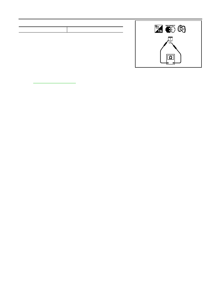
CONDENSER-1
1.
Turn ignition switch OFF.
2.
Disconnect condenser-1 harness connector.
Terminal No. (Polarity)
Resistance
Ω
[at 25
°
C (77
°
F)]
1 and 2
Except 0 or
∞
1 and 3
Except 0
2 and 3
Spark should be generated.
PBIB0847E
BBIA0534E
PBIB2325E
EC-658
IGNITION SIGNAL
2006 Pathfinder
3.
Check resistance between condenser-1 terminals 1 and 2.
Removal and Installation
UBS00KHZ
IGNITION COIL WITH POWER TRANSISTOR
Refer to
EM-32, "IGNITION COIL"
.
Resistance
Above 1 M
Ω
at 25
°
C (77
°
F)
PBIB0794E
Content .. 222 223 224 225 ..
Source: https://zinref.ru/avtomobili/Nissan/041_02_Nissan_Pathfinder_2006_EN_4600_raznie_2/224.htm
Posted by: gasemauriciosays.blogspot.com

Posting Komentar untuk "2003 Nissan Pathfinder Ignition Wiring Diagram"